Printing Parts
Table of contents
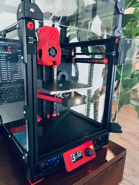
I printed most of my parts on my Voron 0.2. However, with only a 120 x 120 build volume I could only print one part at a time. I had to turn to the ole Ender for some of the larger parts.
![]() Make sure to print everything prior to tearing down your only working printer.
Make sure to print everything prior to tearing down your only working printer.

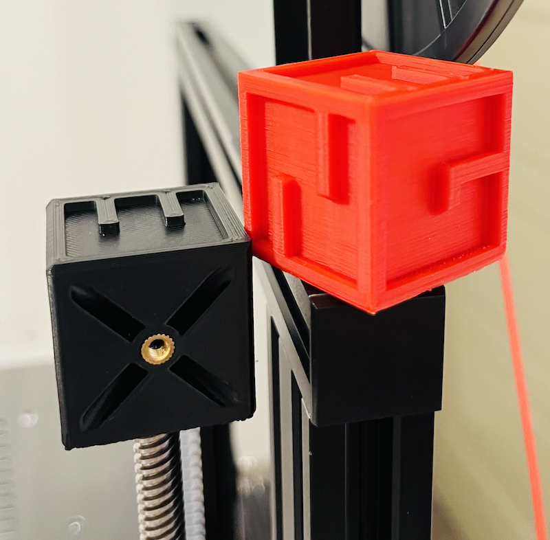
A special calibration cube is included with the project. I printed one off on both my Voron and Ender 3 prior to printing the functional parts. Along with a visual inspection, I used the 8mm threaded rod on my Ender 3 and some spare heat set inserts to check my tolerances.
Materials

I chose to print all of my parts in ABS. ABS is one of the recommended materials and is the Voron standard. I was pleased with the ABS parts I received for my Voron build and I figured I would continue to use it.
Specifically, I used Sunlu Black ABS and Inland Black ABS for the main parts and Fusion Filaments Seismic Red ABS 1.5 for the accent parts. I also picked up a spool of eSun Black ABS+. Allegedly ABS+ is a bit easier to print with and I will be using it to print the large electronics panels on my Ender.
Print Settings
I made some slight modifications to the suggested print settings. Below is a comparison of the E3NG settings and mine:
| E3NG Settings | My Settings | |
|---|---|---|
| Layer Height: | 0.20 mm | 0.20 mm |
| Infill: | 30% | 40% (Cubic) |
| Walls: | 4 | 4 |
| Top/Bottom Layers: | 5 | 5 |
| Extrusion Width: | Not specified | 0.40 mm |
| Supports: | ||
| Brim: | Not specified | As needed |
All of the parts were sliced in OrcaSlicer. My printers and filaments were tuned in accordance to Ellis’ guide.

For reference, the below 3MF files include the printer, filament, and process settings used on my Voron 0.2. They should load into OrcaSlicer with all of the same settings I used.
Printing ABS on the Ender
For the parts unable to fit in the Voron 0.2, I used my Ender 3 Neo.
Full disclosure, my Ender 3 Neo is not stock. Some of the notable changes are:

- BTT SKR Mini E3 V3 Mainboard
- Klipper Firmware
- Input Shaping
- Upgraded NEMA 17 Steppers
- Stealthbuner Toolhead (Currently reduced build volume)
- Clockwork 2 Direct Drive Extruder
- Phaetus Dragonfly BMO Hotend
- Textured PEI Plate
Once again, I included the 3MF files for the parts printed on my Ender 3.
I managed to print these parts without an enclosure using Fusion Filaments Seismic Red ABS for the stepper motor covers and eSun Black ABS+ for the electronics panels. I used a brim and hairspray to assist with bed adhesion. The stepper covers had some mild warping but I do not foresee any issues. The electronics panels printed great, other than not noticing the the E3NG logo inlay ![]() . I guess I’ll add those to my reprinting list.
. I guess I’ll add those to my reprinting list.
Electronics Frame Rims (EF__)
![]() The following covers a modification I made to an STL.
The following covers a modification I made to an STL.

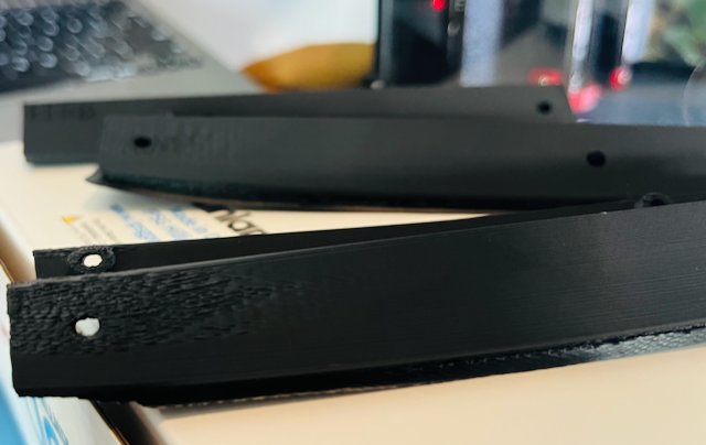
I initially printed the electronics frame rims on the Ender 3 with eSun ABS+ and they came out with terrible warps and tolerance issues.
After reviewing the build manual and STEP file, I noticed these parts are already two pieces that are glued together using the Frame Joint (EFJ). I decided I should be able to split the parts between the mounting holes and reconnect them using additional EFJs. I printed off some extra EFJs and split the rims in OrcaSlicer. The parts printed without issues on my Voron and seemed to mate just fine.
