Electronics
Table of contents
The official documentation does not include information on wiring or installing electronics. The following pages cover the electronics and wiring of my personal E3NG. It should not be considered a standard. It is provided for personal reference and inspiration only.
In addition to the standard printer electronics (steppers, thermistors, & heaters) my build makes use of the following specific components:
- BTT SKR Mini E3 V3 Mainboard
- Raspberry Pi 3A+
- SN65HVD230 CAN Tranciver
- BTT EBB36 CAN Toolhead Board
- LEDs
![]() I later upgraded to a Pi 4 that I had laying around. I ran into some bottlenecks with dev environments on the Pi 3A. The 3A should be fine for just a printer.
I later upgraded to a Pi 4 that I had laying around. I ran into some bottlenecks with dev environments on the Pi 3A. The 3A should be fine for just a printer.
Wiring Guidance
![]() Incorrectly wiring components can cause damage and/or personal injury.
Incorrectly wiring components can cause damage and/or personal injury.
Wires should be routed in a clean manner. This means out of the way of motion components and not pinched, kinked, or otherwise damaged. Always use the correct wire gauge. Securely crimp all connections and use electrical tape and/or heat shrink to prevent shorting. Standard color conventions are especially important for power wires. Label wires as needed.
I provided a table below of the wire gauges I used for various components on the build. Remember, the bigger AWG number, the smaller the wire.
| Component | AWG |
|---|---|
| AC Power | 16-18 |
| DC Power | 18 |
| Heaters | 18-20 |
| Thermistors | 22 |
| Fans | 22 |
| Steppers | 22 |
| Bed Probe | 22-24 |
| CANbus Comms. | 22 |
Main Electronics

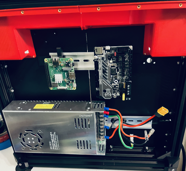
I don’t feel like there is any “right” way to mount the electronics in the rear of the printer. I used a combination of the included DIN clips and some leftover clips from my Voron build.
The large power supply only fit on the lower DIN rail. I was unsuccessful using PSU3 and ended up using the standard DIN1 clip with enlarged holes. In the future I would like to add a buck converter to this lower rail to power the Raspberry Pi. I also need to figure out a more stable way to secure the DIN rail itself.
The upper DIN rail is home to the Raspberry Pi, mainboard, and a CAN transceiver. I used the DIN clips and brackets from my Voron build, simply because they were already printed and on hand.
For the time being, I do not have an enclosure on the rear of the printer. I would like to clean up the wiring and either print or cut a nice panel to cover the back.
Toolhead Electronics
![]() Instead of Klicky, I’m reusing the CR Touch.
Instead of Klicky, I’m reusing the CR Touch.
As previously mentioned, I’m running a Voron Stealthburner for the toolhead. In addition to the usual components (fans, thermistor, and heater) it has some LEDs. I’m also running a BTT EBB36 toolhead board via CANbus. Eventually I will upgrade the CR Touch to a better bed probe and maybe even change the toolhead.

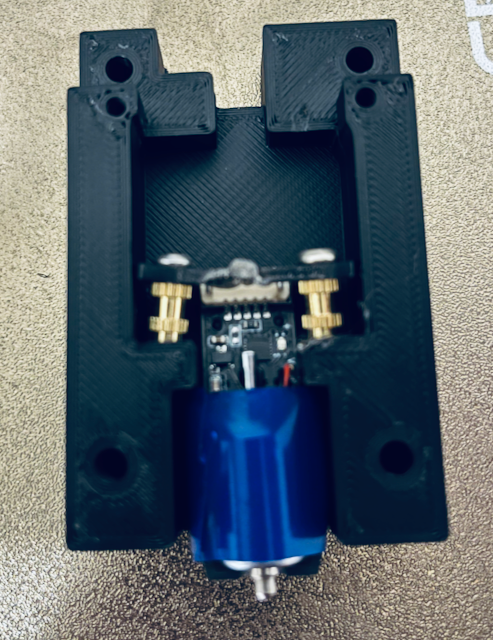
I made some modification to the CR Touch housing and used this mount to attach the Stealthburner to my E3NG. The mount was originally designed for a BL Touch so I needed to shave down and remove some of the CR Touch housing. I also had to add some spacers to the mount.
A more elegant solution would be to redesign a mount that fits the probe correctly. With my currently subpar CAD skills and plans to upgrade the probe, I went with my modification instead.
The big thing to remember with toolhead electronics is to route the wiring an a way that it does not jam up any motion components. The EBB36 CANbus toolhead board helps in this regard. I used one of the many EBB36 mounts found online for the Stealthburner/Clockwork2 then routed and secured loose wires with zip ties.
Bed Electronics
I reused the stock Ender 3 bed including heater and thermistor. This just required routing the existing cables. Future plans include adding some sort of quick disconnect, maybe WAGOs, to make the bed easier to remove along with a cable chain.
Switches and LEDs
The Y endstop switch gets mounted on the A motor mount. Originally I planned to use sensorless homing and still will for the X axis. However I had some issues with the calibarating sensorles homing on the Y So I returned to a standard switch. Keeping with the E3NG spirit, I reused an Ender 3 switch and some wiring. I cut the endstop out of the old mounting board and used some DuPont connectors for the pins. For reference, the X endstop is would be secured to the rear of the toolhead carriage and the Z endstop is screwed into the Z motor mount.
The Stealthburner toolhead already has some integrated LEDs. Other than that, I am planning on mounting some in the print area but have yet to map that out.
LCD Screen
I would like to add a screen. Since I’m using the EXP1 header for CANbus I am still trying to figure this part out.