EBB36 v1.2 Toolhead Wiring
Table of contents
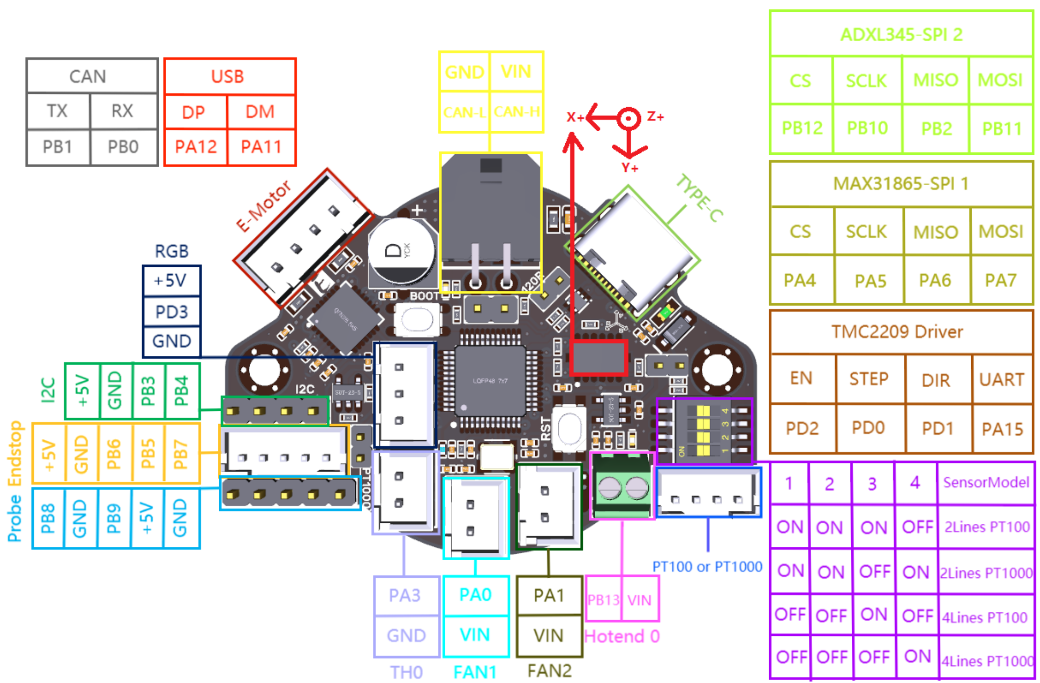
I use BTT’s EBB36 Toolhead board. Once again, schematics and pinout can be found on GitHub and I included a screen shot of the pinout below.

Regardless of USB or CAN communication, the EBB36 requires 24v power. I tapped directly off the main power supply and crimped the included 2x2 Molex Mircofit connector.
![]() The pinout diagram can be a bit confusing. When orienting the EBB36 as shown in the diagram, the rear two Molex pins are
The pinout diagram can be a bit confusing. When orienting the EBB36 as shown in the diagram, the rear two Molex pins are GND and VIN respectively. Miswiring the board can send it up in smoke.
CANbus Wiring
The CAN-L and CAN-H pins should be wired directly to the CANH & CANL pins on the CAN tranciever. On the EBB36, these pins can be accessed either via the Molex connector or the two DuPont pins below it.
CANbus wire harness are available from a number of suppliers. The CAN high and CAN low wires should be a twisted pair. The power wires should not be twisted. Since this was a small run, I twisted my own 22 ga wire and secured it intermittently with zip ties then tucked it into a cable loom next to the 18 ga power wires with everything terminating into the 2x2 Molex Microfit connector at the toolhead.
Terminating Resistor
The CAN network requires two 120 Ω resistors, one at each end of the network. My network starts at the CAN tranciever which happens to have a built in terminating resistor. Most of the time the EBB36 will be the last, or only other, node on the network. A jumper must be placed across the 120R pins to enable the 120 Ω terminating resistor.
E Motor
Plug the extruder motor into this connector. Review the information on stepper motor windings in the previous section.
![]() The EBB36 includes a heatsink that should be placed on the TMC2209 driver. That is the chip just below this connector.
The EBB36 includes a heatsink that should be placed on the TMC2209 driver. That is the chip just below this connector.
RGB
Any toolhead LEDs can be plugged in here. Pay attention to the power and communication pins.
Endstop
I used this connector for the CR touch. The Probe header would have been a drop in fit but required a DuPont connection. I preferred a more secure JST fitting. Just remember to order the pins correctly and this header uses JST 1.5.
Hotend
The thermistor plugs right into TH0 and the heater cartridge used ferrules to screw into Hotend 0. The polarity is not important for these components.
Fans
The part cooling and hotend fans plug into the FAN1 & FAN2 ports. It doesn’t matter which goes where as this can be addressed in firmware.
Other Pins/Components
I am not using the additional headers at this time or the MAX31865 temperature sensor. Setting up the integrated ADXL will be covered in the configuration section.