Mainboard Wiring
Table of contents
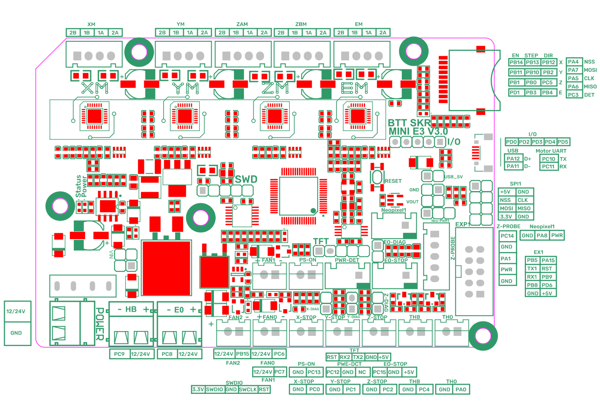
The BTT GitHub provides a pinout and schematics of the SKR Mini E3 v3. I have included a copy of the pinout for reference. Using this diagram, wiring the board is pretty straight forward. Make sure to use the correct pinout for the mainboard in use.

![]() Pay attention to the pin names using during wiring. Example:
Pay attention to the pin names using during wiring. Example: PC9 on the HB terminal for the heated bed. These pin names are used in the firmware to control the components.
I’ve attempted to cover the general wiring of this board in the following paragraphs.
Sections marked with “
” are either specific to or will change based on the use of CANbus and a toolhead board.
Power
I wired the 24v power supply directly to the 24v and GND terminals labeled POWER on the mainboard. Pay close attention to polarity.
Heated Bed
The bed heater was also directly wired to the HB terminal using ferrules and the same wire from the stock Ender 3 bed. The polarity of the bed is not important. In the future, I would like to add a quick disconnect system at the bed side.
The bed therminstor was also wired directly to THB using the original wiring. I did shorten the cable and crimp a new JST connector to the end. Once again, polarity does not matter and I plan to add a disconnect at the bed side.
Extruder 
The extruder heater and thermistor are wired the same as the heated bed but use E0 and TH0.
Fans 
Fans can be wired to any of the 3 JST terminals. Make sure the polarity is correct and the pin name is noted.
![]() If using the stock Ender 3 hotend blower fan with the blue/yellow wires, blue is
If using the stock Ender 3 hotend blower fan with the blue/yellow wires, blue is GND and yellow is 24 VIN.
Endstops
Endstops can be wired to their respective location using a JST connector. Polarity is not as important as it can be corrected in the firmware.
Sensorless Homing
If using sensorless homing, no endstop will be plugged in but rather the DIAG pins will need to be jumped.
Neopixel
LEDs can be plugged into the Neopixel1 port in accordance to the pinout for control in the firmware.
Z-Probe 
The CR and BL Touch probe should be a drop in fit for the SKR Mini E3 v3. However, verify the pinout for all probes prior to connecting.
EXP1 Header
The stock Ender 3 display cable can be used here to power the stock digital style display with Klipper. The color LCD displays do not work out of the box.
CAN Tranciver 
The EXP1 header exposes pins PB8 and PB9 which are the easiest to access for CANbus. I’m running the SKR Mini E3 in USB to CAN bridge mode so I built a custom 2x3 DuPont connector to utilize PB8, PB9, +5V, & GND and connect to a SN65HVD230 CAN tranciver. The table below shows the corresponding EXP1 pins and CAN tranciever pins.
| EXP1 | CAN |
|---|---|
| +5V | 3.3V |
| GND | GND |
| PB8 | RX |
| PB9 | TX |
USB
It’s a MicroUSB port to plug in the Raspberry Pi… The included USB cable should be sufficient.
Stepper Motors
If using the stock Ender 3 motors and stock wiring harness the motors should pretty much be plug and play. If this is not the case, the motor windings need to be identified. The BTT SKR Mini E3 v3 expects one motor winding on the first two pins of the connector and the other winding to be on the last two pins.
Use a multimeter to find the two motor pins with continuity. This can be identified as winding A which means the remaining two pins make up winding B. Crimp a 4 pin JST connector so the first two pins are one of the windings and the second 2 pins are the other winding. The exact location of each wire/winding is not as important since it can be corrected in the firmware.
E & Z Motors 
The extruder and Z axis motors can be plugged into their respective connectors. EM for the extruder and ZAM for the Z axis.
![]() I believe
I believe ZBM would work as well since it is the same motor driver and pinout. My understanding is it allows for a second Z motor to be controlled on the same driver.
A/B Motors
I plugged the A motor, left side motor if looking at the E3NG head on, into XM. That leaves YM for the B Motor. I’m not 100% sure if that is the correct way but it works so I have no complaints.