Mechanical Assembly
Table of contents
The order of steps presented here is how I built my machine. This should not serve as a replacement for the official build manual but rather a supplement. The assembly of the parts is still the same I just reorganized some things and added a few others. I attempted to highlight things that are unique to my build, including the official mods that may not be completely outlined in the manual.
See Preparing Parts for some of the things I did before actually starting the mechanical build.
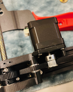
A/B Stepper Motor Mounts
Nothing special here. I just followed the build instructions exactly as written.
Y Gantry
After building these, make sure to keep the M5x50 screws loose enough that the linear rods will fit into the openings. Additionally, I found my tolerance pretty tight on this parts. The LM8LUU bearing snapped in but I needed to bore out the 8mm holes for the rods. ![]() A 5/16” drill is 7.94mm. A little sung but it worked.
A 5/16” drill is 7.94mm. A little sung but it worked.
Additionally, the races of the bearings should be offset 45° in relation to gravity. This helps ensure best performance, smooth operation, and even wear. See the image beloew for reference.

![]() Don’t forget to lubricate the bearings prior to installation.
Don’t forget to lubricate the bearings prior to installation.
Toolhead
Since I am not using the stock toolhead, I only built the back half of this assembly. That meant using XC0, XC1, & XCB along with the LM8LUU bearings and appropriate screws. On second thought, I could have use the appropriate mount plate XC1 for my toolhead of choice right from the start.
![]() There is enough room to change out this part and the toolhead after it has been mounted on the printer.
There is enough room to change out this part and the toolhead after it has been mounted on the printer.
![]() I’m using a standard Voron Stealthburner toolhead along with this remixed
I’m using a standard Voron Stealthburner toolhead along with this remixed XC1 plate. I also modified my CR touch to fit.
Belt Tensioners
I found the bearings to fit fairly sung in my printed pulleys. I used BT1 & BT2 without the external washers to press fit the F695 bearings in place. Once they were fitted, I put the external washers back in place.
Z Axis Belt Tensioner
I built this in accordance to the manual except for the spring. I didn’t have any extra bed springs so I used the old Ender 3 extruder spring.
Bottom Frame
I built each of the frame pieces then attached them to the bottom frame extrusions as I went. Leadscrews were installed last.
Front Corners
These parts require the Z belt be installed prior to capping them off with BLFB & BRFB. Make sure the belt isn’t twisted or tangled. Don’t over tighten the screws holding on the rubber feet as they may just punch through the mount holes on the feet. I used additional washers to help increase the surface area. I held off on installing the leadscrew for now. At this point, I mounted the front corners to the donor 4040 and 2020 extrusions that will form the base of the printer
Rear Corners
I didn’t want to fight with printing the large vertical beams so I used the 350mm 2040 extrusion mod which required the use of BLR_2040_350 and BRR_2040_350. These bolted directly onto the bottom frames X/Y extrusions with M5x12s. I also secured them to the rear 4040 extrusion.
Z Axis Support and Stepper
My build uses the 1040mm Z belt and needed BZA_1040. Its essentially a combination of the Z stepper mount and leadscrew mount. The assembly is similar enough. However once again, it requires the Z belt to be routed prior to completing the assembly of this part so make sure the belt has no twists and follows the correct path.
Completing Bottom Frame Assembly

At this point, the bottom frame has been assembled with each corner bracket. The rear Z support still needs to be attached, leadscrews inserted, and belt tensioned. I attached BZA to the rear extrusion using the T nuts. I bolted the Z tensioner to the right extrusion. While the Z belt was still loose, I inserted each of the 3 three lead screws. When installing the lead screws, make sure they go through both 608 bearings but not so far that it hits the surface below. Secure the lead screws using the grub screws on the three Z pulleys. The Z motor pulley may need to be adjusted so it is level with the screw pulleys. I waited until the mounting the bed before I tensioned and secured the Z belt to each pulley.
Finally, I went ahead and slid the vertical 350mm 2040 extrusions in place and secured them with T nuts. I also screwed the rear rubber feet into holes I tapped on the bottom of these extrusions.
Bed Assembly
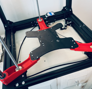
I assembled the bed using the stock plate. Use care when tightening the screws that hold the LM12UU bearings. ZCL is easy to crack. I reused the lead screw nut from the Ender 3. It was not an exact match to the mounting pattern on the printed arms. As a result, I needed use some M2 bolts and a nut to secure it. I will be replacing this particular nut.
Mounting the Bed Assembly

Start by inserting the 12mm linear rods into the bottom frame. Then line up the left and right sides of the bed frame with the lead screws and rods. Next, I slid the Z motor assembly until the rear lead screw was in the correct position and secured the assembly. I alternated turning each lead screw until the bed frame assembly was in the lowest possible position on each arm. I knew for a fact, this would be the lowest point the bed can move. I now routed the Z belt over each pulley and applied tension with the Z tensioner. Now, by turning one screw, I was able to move the bed assembly up and down equally on all 3 screws.
![]() Apply a little grease to the lead screws during this process to keep them clean and running smooth.
Apply a little grease to the lead screws during this process to keep them clean and running smooth.
Follow the manual’s instructions on aligning the bed carriage if the screws don’t sit in the middle of the anti wobble mounts.
Mounting the Build Plate
The stock build plate can be placed over the stock mounting holes. I used my existing bed springs since they were already the yellow ones. I also used the old adjustment wheels. Make sure to use the printed spacer for the front wheels and the rear cable strain relief.
Top Frame Assembly
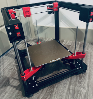
All of the X/Y components have already been assembled, now I put them together and mounted the top frame. Per the manual, I secured the 2020 top rear extrusion and 2040 top side extrusions to the A/B motor mounts. Rather than install the X/Y axis assembly as one piece, I first inserted the 8mm linear rods into the A/B mounts. Next, I assembled the X gantry with the 2x linear rods, toolhead assembly, and 2x Y ends. This gave me the ability to easily adjust the length so the Y gantry ends fit the top frame without binding.
I now mounted the top front corners and placed the entire top assembly on the lower frame. Since I used the 2040 mod, I needed to secure the rear top corners with TJL-2040 & TJR_2040.
Square and Secure

Check each corner of the frame for a square assembly. I used a speed square along with a solid flat surface. Make sure to tighten the bolts securing each corner bracket. Tighten the set screws on the top and bottom front joints that hold the 12mm rods in place. Move the X, Y, & Z axes for their full range of motion to check for binding. Make adjustments as needed.
I also added the top FCB2 and bottom FCB1 frame corner braces at this time.
AB Belt Routing
I routed the A/B belts prior to installing the electronics panels. Partly because it gave me more room and partly because I was waiting on some hardware. Follow the steps in the build manual with a few very important caveats.
- Make sure to leave plenty of excess at each end of the belt. About 5cm is probably a good number.
- Don’t miss the idler that is hidden behind the A/B motors. Its not really visible on from the outside and hard to see on the drawings. Refer back to the A/B Mount building instructions to see it clearly.
- Align the motor pulley with the center of the belt path.
Electronics Panels
Not much to add here. The 2040 mod requires the use of additional T nuts to mount the panels and a shorter DIN rail. I screwed the DIN rails directly to the electronics panels. I would like to find a way to better secure the lower, longer DIN rail as it seems to put a lot of stress on these panels.
Extras
STLs for a spool holder and handles are included in the release files. I will be adding those once I am further along in the build. I feel as if they will be in the way during the wiring phase.
Completion
Give the build a final inspection. Check for cracks or damaged parts. Make sure the joints and mounts are secure. Check that their is still no binding and each axis has a full range of motion. Now is the easiest time to address any issues or replace any parts. I also took this opportunity to mount the toolhead.